中文版中文版MessageContact usSitemapWelcome toShanghai MX-CEKONG Technology Co.,Ltd website!
Hotline 400 662 6286

MX-CEKONG

Your position: HOME > Product > Smart On-Line Densitometer >
Tel: 400 662 6286
  • Instructions of Tuning Fork Resonance
Instructions of Tuning Fork Resonance
Shanghai Meixu MX-MD-115-04 series insertion densimeter adopts insertion installation, which is widely used for medium density detection in pipelines, open tank containers and closed tank containers. The fluid density directly depends on the vibration frequency received by the tuning fork in the sensor inserted in the medium.The built-in temperature sensor provides temperature compensation for the sensor.


Tel:

400 662 6286

1.Summary:

1. Shanghai Meixu MX-MD-115-04 series insertion densimeter adopts insertion installation, which is widely used for medium density detection in pipelines, open tank containers and closed tank containers. The fluid density directly depends on the vibration frequency received by the tuning fork in the sensor inserted in the medium.The built-in temperature sensor provides temperature compensation for the sensor.
2. Scope of application:The density of the measured liquid can be accurately measured by the following equation calculated
D= K0+K1T+K2T2
D= density of uncalibrated medium (kg/m3) T= frequency of vibration (s).
K0, K1, K2= constants
During density detection, the APX301 insertion densitometer can automatically compensate the temperature for the density of the measured medium
(D)
Influence, pressure has no significant effect on density.
 
Parameter feathers:

Measuring range 0.5 – 2.5 g /cc (500 – 2500 kg/m3)
Calibration range 0.5 – 2.5 g /cc (500 – 2500 kg/m3)
Precision ± 0.002 g /cc (± 2 kg/m3)
Repeat ± 0.0002 g /cc (± 0.2 kg/m3)
Operation tem range -50℃ ~ +200℃
Maximum operation pressure 207 bar (3000 psi)
Fluid viscosity range 0 – 20000 cP
Tem-coefficient Less than 0.1 kg/m3/℃ (after adjusted)
Pressure influence Neglectable
Built-in tem sensor digital sensor
Wetted material 316L stainless steel and Hi-alloy
Coating of the fork body Standard type,PTFE or Electrolytic polishing
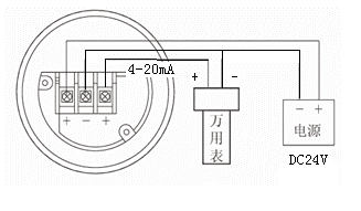
Power supply 24VDC,≥50 mA
Analog signal output 4 -20 mA,0-1000Hz,RS485 Modbus RTU
Output precision(20℃) ± 0.1% or ± 0.05% FS of the number
Output repeatability(-40 ~ +85℃) ± 0.05% FS
 
Process connection
ANSI 150 ~ 1500 RF
DIN 50 PN16   DIN 50 PN40
IDF  and RJT sanitary type
Protection grade IP65
Shell Aluminum alloy

2.Machinery installation:The boundary effect of the wall on the fluid and the viscosity effect of the measuring medium will have some influence on the measurement calibration of the sensor.To overcome these, we summarized and set the installation mode and pipe diameter in advance for different environments, so as to facilitate the selection under the same conditions.

 
Install standard
 
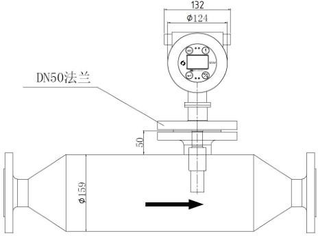
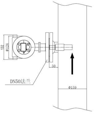
T-shape side open, inserting installation
 
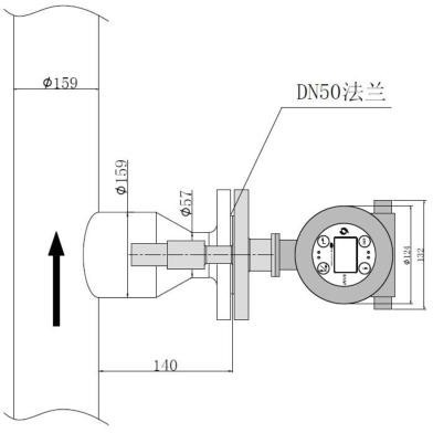
T-shape side open,indented installation
 
Instruction
 
part of the fork goes directly into the main body
The open part of the fork body is indent to avoid the main body
25mm
Velocity The velocity of flow through the fork: 0-1m/s main pipe velocity: 1-5m/s
 
Viscosity range
 
max 20000Cp
 
max  100cP(special conditions can reach 250cP)
Tem -50-150℃ -50-150℃
 
Main pipe size
≥horizontal pipe 100mm(4″);  
≥50mm(2″)
≥vertical pipe 150mm(6″);
 
Advantages
 
easy to install,high precision
 
For mortar fluid, the wear of instrument can be reduced effectively


Disadvantages
  Not applicable:
 
Not applicable:
1. Cottony solution(ex:paper pulp)
 
1.unstable velocity
2. unstable velocity
 
2.main pipe caliber< DN100
3. in cottony solution
4. main pipe caliber< DN100
  5. A condition in which the temperature effect is significant

3.Calculation of flow rate:

V is equal to Q over 1/4 times PI d2.
Example: Pipe diameter of 20m3/h is 100mm
V = 20/3600 / (1/4 * 3.14 * 0.1 * 0.1) = 0.7 m/s

4.Installation and positioning:In order to ensure accurate measurement and stable display of the densitometer, the flow rate of the measured medium shall not be more than 1m/s, and the pipeline diameter of the densitometer shall be greater than or equal to 159mm. The position of the densitometer shall be as far away from the pump as possible, and the distance shall be greater than 5m.When the flow rate is greater than 1m /s, the installation is carried out by means of expanding diameter. For each 1m increase in flow rate, the diameter of the pipeline installed with the densitometer is increased by 1.5 times. Straight pipe sections ≥ 600mm should be installed in front of the instrument and ≥ 300mm behind the instrument, so as to ensure that the fluid is in laminar flow when flowing through the fork body, as shown in the figure


Schematic diagram of horizontal installation of densitometer pipeline


Dimensions for vertical line installation(1)


Dimensions for vertical line installation(2)
 
Schematic diagram of tank installation


An unreasonable installation diagram:


Schematic diagram of unreasonable installation of horizontal pipeline


Schematic diagram of unreasonable installation of vertical pipeline

Electrical wiring diagram:


You can adjust the zero point, range, setting unit, zero point migration, range migration, damping, output characteristics and change the display output by pressing the buttons on the instrument panel.